Ever since I saw the KMG 2" X 72" knife making belt grinder from Beaumont Metalworks I have been wanting one. The Beaumont model is a great design and a great value and I encourage anyone interested in a belt grinder that is not interested in all the work to build one to just go out and buy one. It will be money well spent. These grinders are amazingly versatile and you will find yourself using it almost every time you enter your shop for both metal, and woodwork, or just general tinkering, home repair, etc. If you are interested in gathering some materials together and have a few evenings to spare for construction you will save a bit of money by making your own belt grinder. Truthfully, you will not save enough money to justify the time spent (that really is determined by how much time you have and how much you would earn doing something else with that time), but the satisfaction (I enjoy tinkering on projects like this) of building your own kick ass heavy duty belt grinder is reward in itself. Reading different forums online, I found a lot of information warning DIY people that there were subtle design aspects that were critical and that this was not a simple project. I did not find this to be true. A belt grinder is a simple machine and if you can make accurate measurements, drill perpendicular holes, and use common sense you can build one yourself. I am extremely happy with my build and am posting this information here because it is the belt grinder plan I would have liked to have found on the internet.
Tools Required:
Metal Chop Saw
4 1/2" disc grinder with cutting blades and flap discs for deburring
Drill Press and assorted metal cutting drill bits
Tap and Die set
1 1/4" metal cutting hole saw
Square
Tape Measure
Center punch (spring loaded preferably)
Hammer and Rubber Mallet
Marking Instrument
Welding equipment for tensioner (optional)
Steel for Chassis:
2 pieces 1/2" x 10" x15" Hot Rolled (HR) steel for the verticals
1 piece 1/2" x 10" x 17" HR steel for the bottom
2 pieces 3/4" x 15" square HR steel for the top horizontals
3 pieces 1 1/2" x 1/2" x 15" HR steel for middle horizontals
1 piece 1 1/2" square tubing 3/16" wall thickness x 15" for bottom horizontals and baseplate attachment
2 pieces 1/2" x 1 1/2" x 5" HR steel (optional drive shaft support)
1 piece 1/2" x 10" x 5" HR steel (optional drive shaft support)
1 piece 1/4" plate steel roughly 12" x 5" for tensioner
1 piece 1 1/4" x 12" square bar for tensioner
1 piece 1" x 1 1/4" x 2" steel or aluminum for tensioner pivot
24 gauge sheet metal for shimming
Nuts and bolts to match
Minimum 1 1/2 hp 110/220 1750 RPM motor
3/4" pillow block bearings
Drive pulleys (2-3-4) to match drive shaft and motor arbor and belt
3/4" drive shaft
Tensioner spring
I ordered the tool arms, flat platen, drive wheel, tensioner wheel and small wheel holder from Chaz at knifegrinderparts.com and I cannot recommend him enough. I thought seriously about making my own tool arms, but when I priced just the materials, I found it was well worth it to buy the precision machined ones that Chaz sells. Making a flat platen is not very difficult, but again the one Chaz sells is beeeautiful. You can save money by making your own platen; some people even use roller skate wheels for the contact wheels. The drive and tensioner wheels made by Chaz are exceptional. There is not one single thing that would make any of his products more perfect. That is saying a lot! They are precision machined perfection and the fit and finish is far superior to any others I could find.... I only had enough money to order one small wheel for the small wheel holder and I was a little hesitant to order a whole set since they were not rubber coated, but I feel they work exceptionally well and do not feel the rubberization is necessary for me. Chaz was very helpful and answered any questions I had. Not only that, the order arrived 2 days later! I have no affiliation with knifegrinderparts.com but I like to give credit where credit is due.
 |
| Lower chassis components without the tensioner parts |
Above, you can see the plates for the chassis after drilling. Also you may notice, I recommend closed toe shoes because the plates are very heavy. I will not describe all of the locations of the holes for drilling unless there location is critical. 5/16" bolts were used except for the four bolts which attach the bottom tube which were 3/8".
Bottom plate and tube:
On the far left you can see the bottom plate with the 1 1/2" tubing section bolted onto it. This tube is attached with four 1/2" diameter bolts The bottom plate is drilled and tapped for these bolts. This tube is centered front to back and has a 2" space on the drive side (shown on right here). As you can see the tube was drilled with the hole saw to allow the heads of these bolts to pass all the way through, while the lower hole in the tubing is 1/2" diameter. This may not be necessary but it allow you to use shorter bolts with a direct metal to metal connection with no air space in between that could cause deformation of the tubing. These holes were drilled so that their spacing did not interfere with the 3/8" horizontal holes in the tubing for the attachment of the two large vertical sections shown in the center. The other six 1/2" holes on the plate are drilled so that it may be attached to another baseplate or workbench. I used a piece of 2 x 6 laminated beam for mounting the motor and chassis, but steel or even plywood would work as well
Side Plate Verticals:
I recommend drilling one side plate entirely and then using it as a template to drill the matching plate, top and middle verticals as well as the bottom tube. Because cold rolled tubing has a bit of a rounded 1/2" edge due to the hot rolling process, I mounted the top 3/4" horizontal rail bar down just a little so that it was even with the flat portion of the side plate. This also requires that the top of the assembly be ground down (shown in pictures below) to the level of the top rail to accommodate mounting the tensioner assembly. Once one side plate is drilled entirely the other plate can be clamped to it and two holes can be drilled through the next plate. These holes can then be used to bolt the two plates together and hold them in alignment for drilling all the other matching holes. Perfection is not required here, you can always ream out a few holes if they are misaligned. The top rail and middle rails can be drilled to match the side plate in the same way. I loosely assembled the top section and dropped it on top of the bottom plate and tube to mark exactly where the holes were to be drilled in the bottom tube.
The side plates are drilled so that it can support the 3 horizontal sections of the chassis while providing space for the pillow block bearings for the drive shaft. The pillow block must be spaced high enough so that the drive wheel will not contact the base plate (also allowing extra here is good in case you ever decide to use a larger drive wheel for faster belt speeds). The center hole for the drive axle is drilled with 1" hole saw or drill bit if you have one. The other 4 mounting holes for the pillow block are drilled and tap to match 1/2" mounting bolts. The top and middle horizontal sections are mounted with 5 evenly spaced 5/16" bolts while the bottom section is mounted with four 3/8" bolts. As you can see I used two 3/4" square bars for the top section while the middle was 3 pieces of 1/2" by 1 1/2" bar that were stacked to fill the 1 1/2" space. This is overkill and the middle section could also be made with two 3/4" square bars. You may also choose to make another space beneath the middle rail section so that you can have a separate arm slot for a tool rest instead of mounting the tool rest to the tool arm that the pulleys are mounted to. Don't forget to drill and tap at least one hole (I drilled two as shown) for the tool arm tightening handle. These are the two holes drilled between the top and middle horizontal sections on the
motor side plate
only.
Top Horizontal section:
The two 3/4" square bars are drilled for the horizontal sandwiching bolts. The one on the motor side has two holes drilled and tapped vertically as well, to accommodate mounting the tensioner mechanism's base. The positioning of these holes will be described in the tensioner section.
Middle Horizontal section (toolrest bottom support):
If the Middle section is made of the 1 1/2" stock as shown the rear portion has to be relieved to accomodate the height of the pillow block as shown in the pictures. This is done by drilling a 3/8" hole in the corner and then using a disc grinder with a cutoff wheel to cut out the excess material. The bolts used are 5/16" but I recommend drilling the holes 3/8" in the middle sections so that their is a little play and they can be located perfectly with the tool arm in place.
Optional Bolster Section For Motor Side Pillow Block:
The Beaumont grinder has the drive pulley pillow block mounted on the
outside of the side plates because of the way the machines rear end is built. In my design the pillow block is mounted on the inside, so the drive shaft will not be supported as close to the sanding belt drive pulley. To "Widen" the area of support I chose to add a bolster section to move the motor side pillow block more laterally. This is similar to the widening that the beaumont has in its rear assembly. My machine is heavier and uses more metal than the way the beaumont is made. I think from a mass production standpoint the Beaumont is made to minimize material useage and save a little of the cost of manufacture. Once again, I think the Beaumont is a great design, I do prefer the simplicity of my design and believe it to be a little bit easier to fabricate than the Beuamont KMG. In hindsight, I think this part is not a bad idea but not necessary, so entirely optional.. The motor side pillow block can just be mounted directly to the
outside of the motor side vertical plate. The 3/4" pillow blocks are pretty beefy and provide a lot of support on their own. Sooo, if you choose to add the bolster section, simply drill the 1/2" x 10" x 5" plate that matches the rear section of the verticals and bolster them out with some 1/2" x 1 1/2" x 5" bar that is drilled as shown.
Shimming:
The tool arms that I ordered were 1 1/2" and fit too tightly in the assembly so I had to make some shims for the top, middle, and bottom horizontal sections. I used some 24g. sheet metal from a piece of stove pipe I had laying around and it worked perfectly. Knifegrinderparts.com will machine the tool arms in the size you need if you would like to avoid shimming.
Once all of these components are drilled (your arm will ache from all the drilling!) debur all the holes. They then can be assembled and bolted together. While assembling leave the tool arm in place so that the horizontal rails will be positioned with the correct amount of space for its movement. The nuts should all be located on the motor side so that they do not interfere with the sanding belts.
 |
| Shims and inner pillow block in place. |
 |
| Using the tool arm while assembling the chassis will create a perfect fit for the tool arm. |
 |
| Notice the bolstering sections for the additional side plate |
 |
| Side plate with pillow block installed |
|
|
 |
| Notice the pillow block mounted on the inside of the drive side plate |
Tensioner Assembly:
The tensioner assembly is probably the most complicated component. The drawing above shows all of the necessary dimensions for re-creating the one on my grinder.
The tensioner arm is made of a 1 1/4" x 8" piece of HR steel. I forged the end to give it a little grip and flare. It needs one 5/16" hole drilled for the pivot, another hole drilled and tapped to match the bolt used for the idler wheel adjustment knob. Additionally, it needs a stack of washers that fits the inside of the spring
mounted on the center of the bottom (I had a random piece of round bar that was threaded for this purpose- see pictures). This stack should be located 4" from the tensioner arm pivot point (may vary with springs used). I fabricated the two L shaped pieces of 1/4" steel plate as shown in the drawing above (disc grinder and cutoff wheel). I then used a 1" by 1 1/2" by 2 1/4" piece of aluminum for the swinging axle for the tensioner wheel. The holes for its pivot were located to match the two L shaped plates then a large hole was drilled and tapped to match the axle bolt itself. This piece of aluminum can then be bolted between the two L shaped pieces to hold them in alignment. I then braze welded the :L sections to the tensioner arm so that its center was located 2 3/4" from the pivot point. You could also mig weld here or the L shaped sections could be made heavier so that they could be bolted on if you do not have access to welding equipment.
The bottom section is also made of 1 1/4" square bar that is 6" long. It has 2 bolts vertically through it that allow mounting to the top of one of the 3/4" square bars of the top horizontals. I drilled these holes in the exact center by starting the holes with a woodworking dowelling jig. Conveniently, centering these holes allows the holes of the 3/4" top rails to be centered as well. I also started the holes in the 3/4" bar with a dowelling jig. Then finished the holes on the drill press. The top of the holes were countersunk for allen bolts, but this is not necessary. A hole for another stack of washers for retaining the spring is also required on the top of this bar. Two 5/16" holes are also drilled for the attachment of the side triangular plates as shown.
The triangular side plates are cut out as shown. The location of the holes for mounting to the bottom section 1 1/4" square bar need to be located so that they do not interfere with the vertical holes that attach the square bar to the top horizontal rail.
 |
| Motor side view |
 |
| Tensioner Top View |
 |
| Tensioner Bottom Open View |
 |
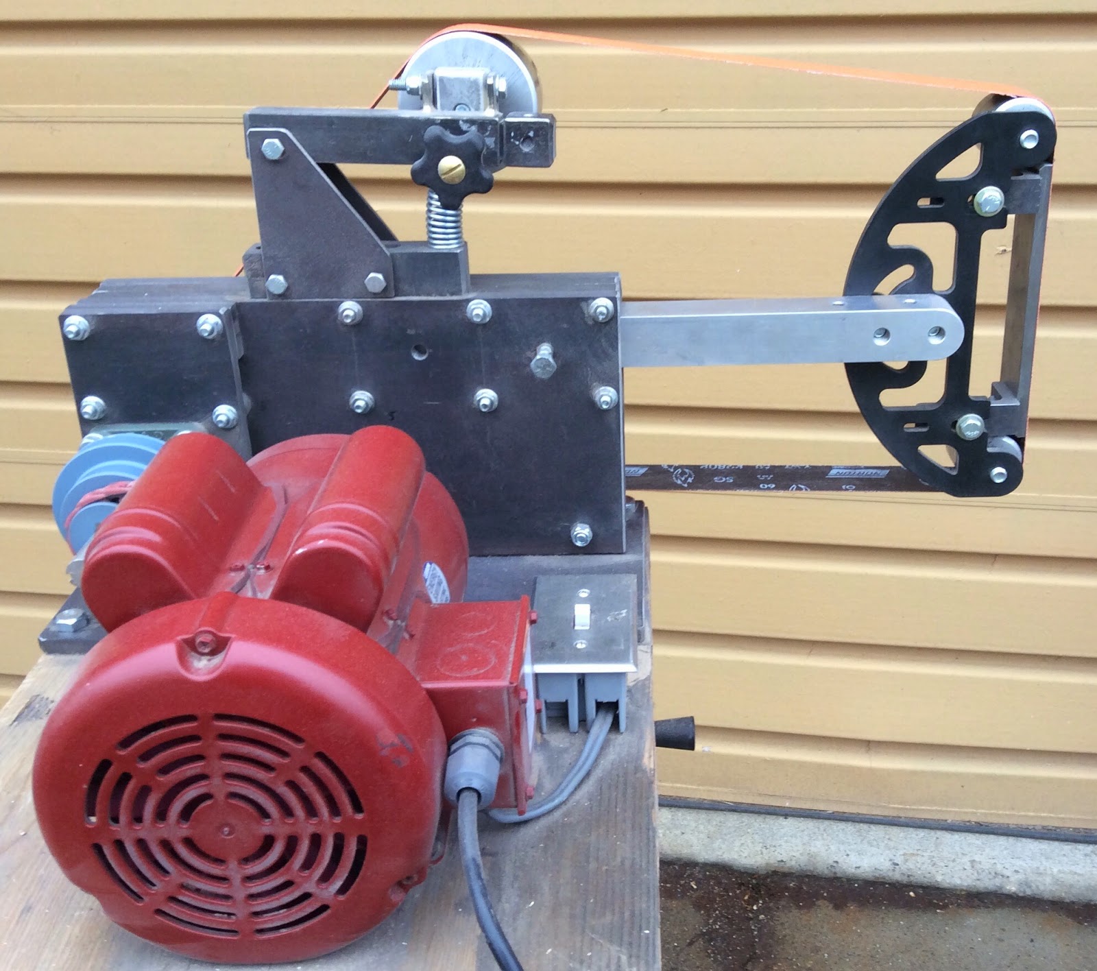
| Tensioner Drive Side View |
 |
| Drive View |
 |
| Sweet Platen! |
 |
| Small Wheel Holder with 1/2" Wheel |
|
|
|
Cost:
I would like to break down the cost of this machine comparing it to the Beaumont
. I would like to just compare the cost of the chassis with the flat platen since I think this is a very economical starting point and allows for different motors, vfd's etc. The cost of the Beaumont chassis with the flat platen is 750 dollars plus 90 dollars shipping so 840 dollars.
Here are the costs of my grinder and flat platen (costs include shipping):
Flat Platen: 130
Tool Arm: 50
Drive Wheel: 50
Idler Wheel: 50
Metal Plate: 80-100 depending on how much you are able to scrounge
Hardware: 50 includes springs, keys, nuts and bolts
Pillow Bearings 16 (Ebay)
Drive Shaft 25 (Ebay)
Total: 451$ Sweet! you just saved 400 dollars.
Additional supplies to get this bad boy running:
Motor 225 Ebay
Pulleys 80 Ebay- Maska/Baldor pulleys are nice but heavy I think I would go with aluminum
V-Belt 25 Harbor Freight or Amazon
Electrical 25
Sand Belts you can spend as much as you want here I like trugrit.com
Total: 355$
Grand Total: 806$ I defy you to find a better grinder for the money!
Conclusion:
If I could change one thing, it would be to get a 5" drive wheel. I assumed I would use this grinder on the lowest speed most of the time, but I actually use it on the highest speed all the time. A larger drive wheel would give me one speed higher and maybe a lower speed that I would find useful. I think this is a great design, it is extremely heavily built and should last many lifetimes although I may ask to be buried with it!